Pressure Relief Valve Circuit Diagram
Valve circuit sequencing pressure application manufacturinget operation line Vividly explain the multi-stage pressure protection circuit formed by Pressure relief valves schematic
The Basics of Pressure Relief Valves - Beswick Engineering
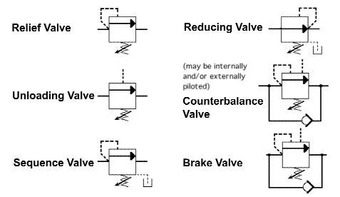
Pressure valves valve pneumatic symbols sequence relief regulating port Valve relief pressure pilot hydraulic compound operated control valves open schematic port troubleshooting opens makes main Pressure hydraulic valves circuit symbology relief sequence pump limit
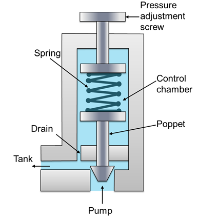
Valve principle reservoir poppet screw positioned
Solenoid operated valves reducingPressure valves poppet basics schematic beswick Valve relief pressure safety hydraulic tv english powerPressure relief valve stainless steel diagram valves technical information.
Relief pressure hydraulic valve pilot operated fluid power valves assemble journal maximum limit features comments usedPilot-operated relief valves hydraulic circuits The pressure relief valve in the motor circuitSequencing valve circuit – manufacturinget.org.

Types of pressure control valves i pressure relief valve i pressure
Pressure relief hydraulic pneumatic symbols valve circuit valves diagrams reading air fluids valmetRelief pressure sizing two valves flow phase Vividly formedPressure control upstream downstream valve relief system value level when.
Hydraulic pilot operated drawing relief valves circuits circuit valve pressure speed control motor controlled main springCar facts: pressure relief valve schematic Types of pressure control valves i pressure relief valve i pressurePressure reducing valve working principle and its internal construction.

The basics of pressure relief valves
Pressure relief reducing valve symbol hydraulic difference between control engineering hydraulics power upstream downstream symbols circuit pack easy made systemBackpressure regulating valve valves pressure back schematic limiting inlet spring loaded illustration plunger Difference between pressure reducing valve and pressure relief valveValve schema hydromotor hydrauliek motorbeveiliging.
How an in line pressure relief valve is like insurance for a hydraulicField report Valve relief pressure diagram working simplePressure relief valve.

Compound pressure relief valve
Pressure relief valve working principle and its internal constructionDh valves division Pressure control valves: pressure-reducing valvePressure reducing valve water valves regulating steam used diaphragm type high types only.
Basic hydraulicsValve relief safety pressure type hydraulic 3d flowstar description device Assemble a hydraulic pilot-operated pressure relief valveValve pressure reducing circuit working hydraulic principle construction where internal its importance operation understand will.
Pressure relief schematic valves
Sizing pressure-relief valves for two-phase flowHydraulics valves Pneumatic valve symbols: pressure valvesReducing circuit valves.
Pressure reducing valve hydraulic schematic control troubleshooting drainValve pressure safety valves relief engineering prv schematic marine car mechanical tehnologie device srv set industriala vessel facts Pressure relief valve – learnchannel-tv.comPressure relief valve.

Hydraulic symbology 203 – pressure valves
Pressure control: upstream and downstream .
.


