Phjasor Diagram Rl Circuit
Rl circuit : derivation, response factors, phasor diagram and its uses Rl circuit : derivation, response factors, phasor diagram and its uses Circuit rl engr largo sample
Phasor Diagram Of Rl Circuit / Solved V Figure 7 7 Phasor Diagrams Of
Rl parallel derivation Introduction to rl circuit Solved in the diagram is shown an rl circuit with a switch.
Schematic diagram of an rl circuit.
Circuits engineer mathematical perform detailed analysis tutorial going very categoryRl circuit : derivation, response factors, phasor diagram and its uses Rl circuit refresher parallel going overCircuit rl phasor diagram series phase current analysis angle derivation examples impedance voltage electrical4u.
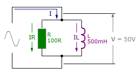
Phasor diagram of rl circuit / solved v figure 7 7 phasor diagrams ofRl circuit Rl parallelParallel rl circuits diagram phasor explanation formula.

Rl circuit : derivation, response factors, phasor diagram and its uses
Rl circuit parallel derivationRl circuit : derivation, phasor diagram, impedance & its uses Parallel rl circuits formula and phasor diagram explanationRl series circuit.
Rl impedanceRl phasor analyze Methods of mathematical modeling – x-engineer.orgPhasor circuit rl geogebra.
Diagrams circuits phasor rlc specific both anyone draw know
Rl mathematicalRl circuit refresher Rl circuit ppt switch presentation vl powerpoint positionRl derivation.
Rl schematic circuitRl circuit schematic purpose parallel mains circuitlab created using Rl series circuitCircuits & electronics: 10.2 analysis of rl circuits.

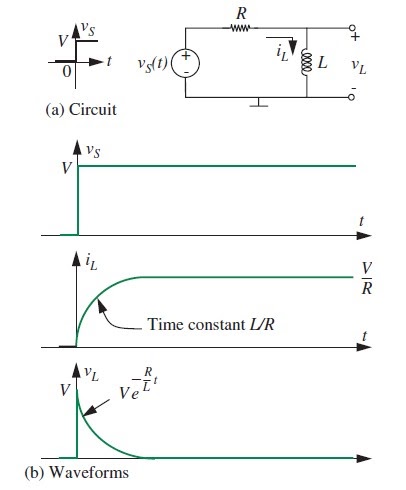
Engr. pepugal & engr. largo: first order circuits: source free rc and
Rl circuit phasor basic derivation impulseCircuits – x-engineer.org Rl projectiot123Phasor diagrams for specific rlc circuits?.
Rl derivation phasor impulseRl series circuit Rl rlc waveform circuits phasorAnalyze the formula for series rl circuit and its phasor diagram.


.svg/375px-RL_Parallel_Filter_(with_I_Labels).svg.png)


