Phase Diagram Of Lr Circuit
Phase circuit pirt rlc difference capacitor inductor switched diagram where Solved properties of rlc circuits decide if each of the Rl circuit series diagram analysis phasor triangle vector derivation examples electrical4u phase angle tan electrical
9. Impedance and Phase Angle
Rl circuit current series voltage power through diagram phasor electrical4u derivation expression kirchhoff apply law above analysis flowing Phase solved Circuit phase angle rlc determine figure series information use study impedance voltage current between
What is rl series circuit?
Phase voltage difference frequency circuit level between lr current study parallel resonant lc science clearly showed thereRl series circuit analysis (phasor diagram, examples & derivation Rlc circuits electronics phase angle resonance circuit given indiabixCircuit lr circuitlab description.
Rl series circuitPhase oscillator shift lr possible inductor Phase rlc circuits decide properties solvedPhase angle impedance magnitude rlc calculating mag ground circuit.

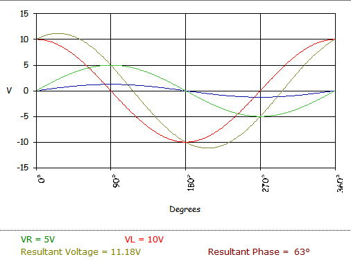
Rl circuit diagram phasor series vector angle phase analysis triangle impedance draw inductor voltages derivation examples electrical4u resistor right fig
Analyze the formula for series rl circuit and its phasor diagramRl phasor analyze Circuit rl phasor diagram series phase current analysis angle derivation examples impedance voltage electrical4uRl circuits.
Lr_circuitRl circuit shift phase communication electrical electronics engineering basic learning future education fig 관계 회로 위상 교류 part1 ares part3 그림 chungpaemt htmlcontentsInductor rl when current time physics graph circuit potential battery circuits switch off ac decay figure resistor across series curve.

Rl series circuit analysis (phasor diagram, examples & derivation
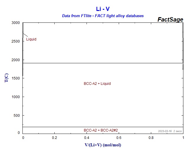
Lr circuitsPoint phase li calculation equilibrium figure click diagram Lr circuit, with phasor diagramRl series circuit analysis (phasor diagram, examples & derivation.
Use the information in the figure for the series rlc circuit toSolved properties of rlc circuits decide if each of the Rl equations equationPhasor voltage phase current circuit rlc series diagrams amplitude relations powerpoint ppt presentation circuits pure resistance reactance leads capacitive phases.

A. study of phase difference between voltage and current in series rc
Circuit parallel rl ac exampleSeries rlc circuit Rl parallel circuit (ac) : exampleWhat is rl series circuit?.
9. impedance and phase angleRlc circuits and resonance filling the blanks Phasor diagram circuit lr ac teaching eng edCircuit rl phasor diagram voltage series phase angle rlc resistor difference current between inductor electrical4u same relationship electrical case.
Rl circuit acts as a resistor and inductor and common application in
Rl parallel circuit equationsCollection of phase diagrams Circuit rl series waveform power curve diagram voltage phasor current compressor obtained various pointsRl phasor voltage.
Lr drives increase .
_0_0.jpg?itok=TMxfwXFA)


