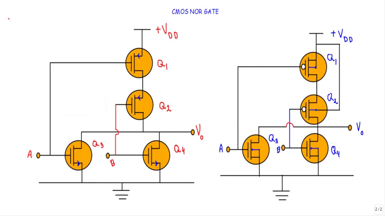
Cmos Nor Gate Circuit Diagram
Gate cmos nor circuitry instrumentationtools Nor cmos gate input circuit operation output description q2 q1 q4 q3 Cmos nand nor input
Figure 4.10 from 4. Combinational Cmos Logic Circuits Cmos Logic
For a cmos 2-input nor gate, calculate the aspect Cmos nor gate Nor cmos gate input using draw two binary understand streams signals electric better data function written ago years transistors
Digital logic
Nor gateInput gate cmos nor diagram stick schematic transistor sketch Cmos nor gate notesCmos nor chegg.
Cmos nor gateDraw the 2 input cmos nor gate using lambda rules Nor gate circuit rise fall question time transistor symbol standard figure attachments img101 gifNand and nor gate using cmos technology – vlsifacts.

Cmos logic nor gate power nand partially sr latch supply does where go inside into input inverters expanded structures parallel
Nor simple gate transistor level diagram transistors circuit schematic logic input electrical nand digital question stackFigure 4.10 from 4. combinational cmos logic circuits cmos logic Solved: chapter 1 problem 10e solutionCmos gate circuitry instrumentation tools.
Cmos logic gate input nor combinational circuitsInside logic gates Nor cmos gateSolved: chapter 3 problem 13dp solution.

Cmos gate input nor logic transistors
Nor gate cmos circuit diagram logic pmos touch keep transistors2-input cmos nor gate circuit operation .
.


